How do you improve MIG and MAG pipe welding?
Posted onMaster MIG and MAG pipe welding with four proven factors that eliminate cracks, porosity, and costly rework.
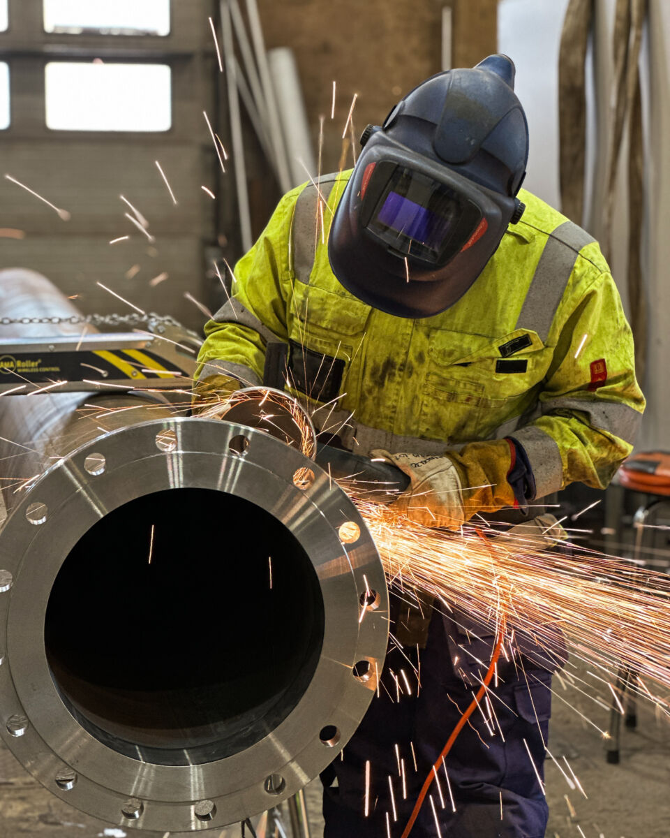
You can improve MIG and MAG pipe welding by combining correct joint preparation, appropriate shielding gas selection, stable wire feed settings, and proper pipe handling throughout the process. These four factors work together, and a weakness in any one of them shows up directly in the finished weld. Whether you are welding in a prefabrication workshop or on a job site, the principles stay the same. Below, we cover the most common questions welders and supervisors ask when they want to get better results from pipe welding.
What are the key differences between MIG and MAG welding on pipes?
MIG welding uses an inert shielding gas such as argon or helium, while MAG welding uses an active gas such as CO2 or a mixed gas containing CO2. On pipes, this difference directly affects arc stability, spatter levels, and the mechanical properties of the finished weld. MIG is typically used on non-ferrous metals and stainless steel, while MAG is the standard choice for carbon and low-alloy steel pipes.
In practice, MAG welding with a mixed gas such as 82% argon and 18% CO2 (commonly called M21) gives you a stable arc with lower spatter than pure CO2, while still providing the oxidizing effect that improves fusion on steel. Pure CO2 is cheaper but produces more spatter and a rougher bead profile, which can mean more cleanup time.
For stainless steel pipes, MIG welding with a tri-mix gas or a high-argon blend protects the weld pool from oxidation and preserves corrosion resistance. Choosing the wrong process for your base material is one of the most common reasons pipe welds fail quality inspection, so matching the process to the material is not optional.
How does joint preparation affect MIG and MAG pipe weld quality?
Joint preparation has a direct and measurable effect on MIG and MAG pipe weld quality. Poorly prepared joints lead to inconsistent root gaps, misalignment, contamination, and incomplete fusion. A well-prepared joint gives the welder a consistent, repeatable starting point and reduces the chance of defects in the root pass and subsequent fill passes.
Alignment and fit-up
Pipe alignment is one of the most common sources of weld defects. Even small amounts of misalignment at the joint create uneven wall thickness across the weld, which can cause incomplete penetration on one side and burn-through on the other. Using centering collars during fit-up removes guesswork and holds the pipes in the correct position while tack welds are applied. AMA’s centering collars are available for a wide range of pipe sizes and are designed to reduce installation errors to a minimum.
Surface cleanliness
MIG and MAG processes are sensitive to surface contamination. Oil, moisture, mill scale, rust, and paint all introduce hydrogen and other gases into the weld pool, which leads to porosity and cracking. Before welding, clean the joint area with a grinder or wire brush, and degrease with a suitable solvent. This step takes a few minutes but prevents defects that take much longer to repair.
What shielding gas settings work best for pipe welding?
For MAG welding of carbon steel pipes, a mixed gas of 75 to 82% argon with the remainder CO2 gives the best balance of arc stability, low spatter, and good mechanical properties. For MIG welding of stainless steel pipes, a high-argon mix with 2 to 3% CO2 or a tri-mix gas (argon, helium, CO2) is widely used. Gas flow rate typically ranges from 12 to 18 liters per minute depending on nozzle size and site conditions.
On job sites exposed to wind or drafts, you may need to increase the flow rate or use a gas lens to maintain adequate shielding at the weld pool. However, increasing the flow rate too much creates turbulence that actually draws in atmospheric air and worsens shielding. A flow rate above 20 to 25 liters per minute rarely improves results and often makes them worse.
For stainless steel pipes, back purging is also important. When welding the root pass on stainless steel, the inside of the pipe must be purged with inert gas to prevent oxidation on the back of the weld. Oxidation on the root side reduces corrosion resistance and can cause the weld to fail in aggressive process environments. Purge plugs and purge kits make this process faster and more reliable by forming an airtight seal inside the pipe and reducing the volume of gas needed.
Why do pipe welds crack or develop porosity?
Pipe welds crack or develop porosity primarily because of hydrogen contamination, inadequate shielding, poor joint preparation, or incorrect heat input. Each of these causes a different type of defect, and identifying which one you are dealing with helps you fix the root cause rather than just the symptom.
Porosity
Porosity in MIG and MAG pipe welds is almost always caused by gas being trapped in the solidifying weld pool. The most common sources are surface contamination (oil, moisture, rust), insufficient shielding gas coverage, a damaged or blocked gas nozzle, or a gas flow rate that is too high and creates turbulence. Check your consumables and gas delivery system first before assuming the problem is technique.
Cracking
Cracking in pipe welds falls into two main categories: hot cracking and cold cracking. Hot cracking occurs during solidification and is often linked to high sulfur or phosphorus content in the base material, or to a weld bead that is too narrow and deep relative to its width. Cold cracking, also called hydrogen-induced cracking, occurs after the weld has cooled and is caused by hydrogen absorbed during welding combined with residual stress. Preheating the pipe before welding reduces the risk of cold cracking on thicker wall sections and higher-strength steels.
What pipe handling tools improve MIG and MAG welding results?
Pipe handling tools that keep the pipe positioned correctly and rotating at a controlled speed directly improve MIG and MAG welding results. When a welder can work in a fixed, ergonomic position while the pipe rotates, the weld bead is more consistent, heat input stays even, and the risk of positional defects drops significantly.
A pipe rotator is the most impactful tool for improving weld quality in a prefabrication workshop. The AMA Roller pipe rotator rotates pipes from 30 to 508 mm in diameter at a controlled speed, so the welder stays in one ergonomic position throughout the entire circumferential weld. The result is a seam that closely resembles a robotic weld in consistency, without the capital cost of automation.
Explore the AMA Roller pipe rotator and see full technical specifications:
AMA Roller Standard Pipe Rotator
For situations where the welder needs to move freely around the pipe or work at a distance, the AMA Roller Premium with wireless Bluetooth control allows rotation speed and direction to be adjusted from up to 25 meters away. This is particularly useful on larger job sites where trailing cables create hazards and slow down work.
Pipe stands, centering collars, and counterweight systems also contribute to better welding outcomes by keeping pipes stable and correctly aligned during fit-up and tack welding. Tools that seem like they only save time often also improve quality, because a stable, well-aligned pipe simply gives the welder better conditions to work in.
How do you choose the right wire feed speed and voltage for pipe welds?
Wire feed speed and voltage must be matched to your wire diameter, base material, wall thickness, and welding position. As a starting point, higher wire feed speed increases deposition rate and heat input, while voltage controls arc length and bead profile. The two settings interact, so adjusting one without the other changes the balance of the weld.
For a 1.0 mm wire on carbon steel with M21 gas, a typical starting range for the root pass on thin-wall pipe is around 4 to 6 meters per minute wire feed speed with 17 to 20 volts. Fill and cap passes on thicker walls use higher settings. These are starting points, not fixed rules. Your specific wire brand, shielding gas, and machine characteristics all affect the ideal settings.
A useful practical check is the sound of the arc. A stable MIG or MAG arc on pipe produces a consistent crackling sound without irregular popping or sputtering. Popping usually means the voltage is too low for the wire feed speed, while excessive spatter often means the voltage is too high or the gas coverage is inadequate. Adjust one parameter at a time and run a short test bead on scrap material before committing to production welds.
On pipe welds specifically, the welding position changes as you move around the circumference if you are welding in a fixed position. In a 5G or 6G setup, you move from overhead through vertical to flat, and each position ideally needs slightly different settings. Using a pipe rotator to keep the weld in the flat or slightly downhill position throughout the pass removes this complication entirely and makes parameter selection much simpler.
Improving MIG and MAG pipe welding comes down to controlling the variables that matter most: material preparation, gas selection, parameter settings, and pipe handling. At Welner, we design and manufacture AMA pipe handling tools specifically to help welders and teams work more accurately and efficiently, whether in a prefabrication workshop or on a job site. Our product range covers pipe sizes from small-bore to large-diameter industrial applications, and we have authorized dealers across Northern Europe, Western Europe, and Central Europe. Find your nearest dealer and see the full product range at AMA authorized dealers. If you have a specific application or want to talk through which tools fit your workflow, contact us directly and we will help you find the right solution.